
Buck Converter Calculator
Output
About Buck Converter Calculator
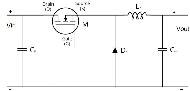
The Buck Converter Calculator determines two key design parameters for an ideal buck converter:
- Duty Cycle (D): In an ideal buck converter, the output voltage is related to the input voltage by
\[V_{out} = D \times V_{in}\] so that \[D = \frac{V_{out}}{V_{in}} \times 100\%\] (expressed as a percentage). - Inductance (L): The inductor is chosen to limit the ripple current (\(I_{ripple}\)) according to the formula:
\[L = \frac{(V_{in} – V_{out}) \times \left(\frac{V_{out}}{V_{in}}\right)}{I_{ripple} \times f_{sw}}\]
Important: For a buck converter the input voltage must be greater than the output voltage. If not, an error message will be shown.
Example Calculation
Example
- Vin = 12 V
- Vout = 5 V
- fsw = 500 kHz
- Iripple = 1 A
Duty Cycle: \[D = \frac{5}{12} \times 100 \approx 41.67\%\]
Inductance: First, express the duty cycle as a fraction: \(D_{frac} = \frac{5}{12} \approx 0.4167\). Then, using the formula: \[L = \frac{(12 – 5) \times 0.4167}{1 \times (500\times10^{3})} \approx \frac{7 \times 0.4167}{500\,000} \approx 5.83\times10^{-6}\,H\] which is about 5.83 µH.