RLC Circuit Impedance and Phase Calculator
| Impedance (Z) | Phase (Φ) |
|---|---|
| 0 | 0 |
RLC Circuit Impedance and Phase Calculator
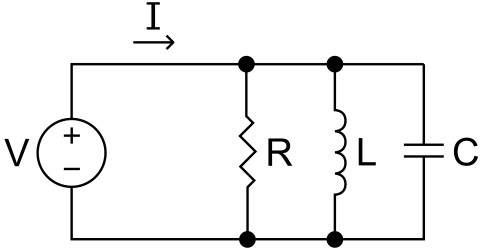
An RLC Parallel Circuit consists of a resistor (R), inductor (L), and capacitor (C) connected in parallel.

The impedance (\(Z\)) of an RLC circuit determines its opposition to AC current, while the phase angle (\(Φ\)) indicates the phase difference between voltage and current.
Impedance is calculated as:
\[Z = \sqrt{R^2 + (X_L – X_C)^2}\]
- \(R\): Resistance in ohms (Ω)
- \(X_L\): Inductive reactance (\(X_L = 2\pi f L\))
- \(X_C\): Capacitive reactance (\(X_C = \frac{1}{2\pi f C}\))
The phase angle (\(Φ\)) is given by:
\[ Φ = \arctan\left(\frac{X_L – X_C}{R}\right)\]
The phase angle indicates whether the circuit is inductive (positive \(Φ\)) or capacitive (negative \(Φ\)).
Example Calculation
Consider an RLC circuit with the following values:
- Resistance (\(R\)) = 50 Ω
- Inductance (\(L\)) = 10 mH = 0.01 H
- Capacitance (\(C\)) = 1 µF = \(1 \times 10^{-6}\) F
- Frequency (\(f\)) = 1 kHz = 1000 Hz
First, calculate the reactances:
- \(X_L = 2\pi f L = 2\pi (1000)(0.01) = 62.83 \, \Omega\)
- \(X_C = \frac{1}{2\pi f C} = \frac{1}{2\pi (1000)(1 \times 10^{-6})} = 159.15 \, \Omega\)
Next, calculate impedance:
\[Z = \sqrt{R^2 + (X_L – X_C)^2} = \sqrt{50^2 + (62.83 – 159.15)^2} \approx 115.88 \, \Omega\]
Finally, calculate the phase angle:
\[Φ = \arctan\left(\frac{X_L – X_C}{R}\right) = \arctan\left(\frac{62.83 – 159.15}{50}\right) \approx -1.16 \, \text{radians} \, (-66.55^\circ)\]
